Settings
- Omar Lamrani
- Solutions Geo-Plus (Unlicensed)
- Anonymous
Menu: Preferences / Edit preferences
This interface allows the user to personalize the settings for VisionLidar. This section is divided into many sub-sections:
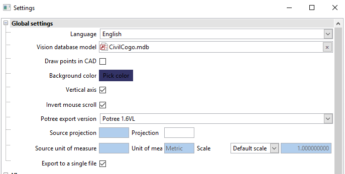
Settings / Global settings:
Language: Select English, French or Spanish to view the software in the specified language. Information linked to the project, however, will not be translated - such as the name of classes and objects.
Vision DB model: This is the model file used to create a new Vision database. The configurations used in virtual surveying come from this model. By default, the CivilCogo.mdb file is selected (which contains the Vision+ configuration), but this can be modified here.
- Draw in CAD: When activated, if VisionCivil is open on a CAD platform with the same database, the points and chains will automatically be drawn in it upon saving.
Background color: Color of the background in the different point cloud visualisation windows.
Vertical axis: This option fixes the vertical axis when rotating the view, keeping the global orientation of the model.
Invert mouse scroll: Reverses the zoom direction when using the mouse wheel.
Potree export version: Version for exporting Potree web viewing format. Current formats available: 1.4RC and 1.5RC.
- Source projection: Projection of the point cloud's system of coordinates in the EPSG code.
- Source unit of measure: Unit of measures of the point cloud's system of coordinate. The scale option allows to change every fields and measurements to show the new scaled unit instead of the source unit system.
Export to a single file: This option allows the user to export their files as a single file or, if multiple scans are present in the project, export using the same number of files in the project. When exporting multiple files, an additional prompt will appear asking the user how to name their files.
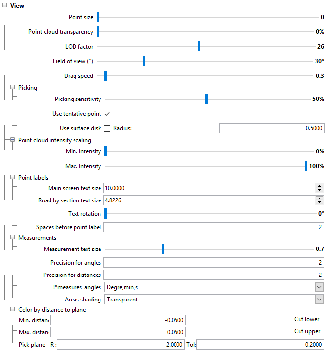
Settings / View:
View (general)
Point size: Modifies the size of individual points in the point cloud.
- Point cloud transparency: Allow the points to be translucide, enhancing the combination of spherical photos and point clouds visualization.
LOD factor: Adjusts the distance coefficient to determine when to load levels of detail of the point cloud. A higher coefficient will load more details while being farther from the point of view. A higher LOD factor will load more points and necessarily affects the fluidity of the software, depending on the speed of the computer being used.
Field of view (deg): Visual angle used for visualization. A higher FOV value will enhance the graphical distance between points that are further from the perspective center. This will create a certain distortion while enabling larger visibility. On the other hand, a smaller value will restrict the field of view, creating a near isometric view. The default value of 30 is best adapted to the visualisation tools.
Drag speed: Controls the dragging speed of points when editing a cross-section with the “Road by sections” tool.
- Picking
- Picking sensitivity: Sensitivity for points to be picked when clicking on the point cloud
- Use tentative point: When activated, pressing CTRL when picking point and maintaining each press, allow to rotate the view and validating. Releasing CTRL first will accept the point while releasing the mouse button first will let the user pick another point instead.
- Use surface disk: When activated, a disk representing the local plane where the cursor is will appear.
- Point cloud intensity scaling
- Min. Intensity: Recalibrate the intensity scale by enhancing the minimum value.
- Max. Intensity: Recalibrate the intensity scale by decreasing the maximum value.
Point labels
Main screen text size: Label size for points in the main VisionLidar window.
Road by sections text size: Label size for points in the “Road by sections” secondary window.
Text rotation: Text rotation for points in the “Road by sections” secondary window.
Spaces before point label: Spaces between the node and the point label in the “Road by sections” secondary window.
Measurements
Measurement text size: Size of text for the “Measure distance” and “Measure angle” functions.
Precision for angles: Decimal digits used for angle measurements.
Precision for distances: Decimal digits used for distance measurements.
- Angle unit: Allow to change the units in decimal degrees, radiant or degrees min sec.
- Areas shading: Allow the fill of areas to be transparent, translucide, opaque or no shading.
Color by distance to plane
Min. Dist.: Default value for the minimal distance between a point and a plane in the “Color by distance” function.
Max. Dist.: Default value for the maximal distance between a point and a plane in the “Color by distance” function.
Cut lower/cut upper: Default state of the “Cut lower/cut upper” options in the “Color by distance” function.
Pick plane R: Default value of the search radius used to detect planes around a picked point
Pick plane Tol: Default value of the tolerance used for detecting planes.
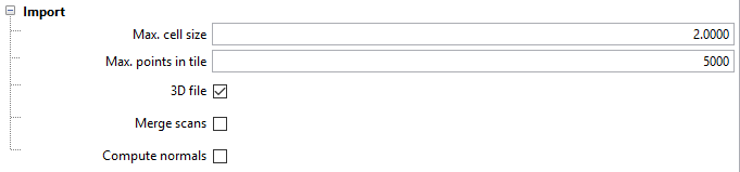
Settings / Import
- Max. cell size: Set the default value in the project creation.
- Max. points in tile: Set the default value in the project creation.
- 3D file: Set the default value in the project creation.
- Merge scans: Set
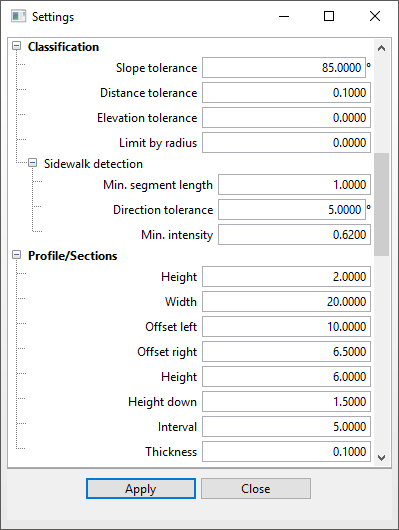
Settings / Classification:
Classification (general)
Slope tolerance: Default slope tolerance value for the classification functions.
Distance tolerance: Default value for the size of tiles to be analysed in the classification functions as well as the distance tolerance in the “Edge detection” and “Line by intensity” functions.
Elevation tolerance: Default value for the distance tolerance from the plane in the classification functions as well as the elevation tolerance “Edge detection” and “Line by intensity” functions.
Limit by radius: Default value for the “Limit by radius” option in the classification functions.
Sidewalk detection:
Min. seg. Length: Default value for the minimum segment length in the “Edge detection” and “Line by intensity” functions.
Direction tolerance: Default value for the tolerance direction in the “Edge detection” and “Line by intensity” functions.
Min. intensity: Default value for the minimal intensity used.
Settings / Profile/Sections:
Height: Default height of profiles and sections in the “Analyze/Profiles / Sections” menu.
Width: Default width of sections.
Offset left: Default left offset in the “Road by sections” function.
Offset right: Default right offset in the “Road by sections” function.
Height: Default maximum height in the “Road by sections” function.
Height down: Default minimum height in the “Road by sections” function.
Interval: Default value of the interval between each profile or section, or the interval used with the “Road by sections” function.
Thickness: Default thickness of a section view for profiles, sections and sections in the “Road by sections” function.
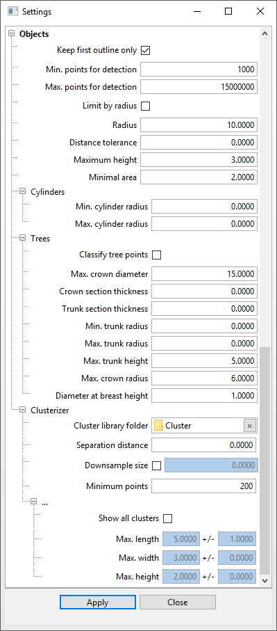
Settings / Objects:
Objects (general)
Keep first outline only: Keep the first outline or not.
Min. points for detection: Default value of the minimal number of points required to detect an object.
Max. points for detection: Maximum number of points to process automatic tree detection algorithms. This value limits the processing time since the function could process for a very long time to treat all data in the project.
Limit by radius: Default value for the “Limit by radius” option for object detection.
Radius: Default radius value used for the “Limit by radius” option.
Distance tolerance: Default value of the distance tolerance for object detection.
Maximum height: Default value of the maximum height for object detection.
Minimal area: Default value for the minimum area for object detection.
Cylinders
Min. cylinder radius: Default minimum radius for cylinder detection.
Max. cylinder radius: Default maximum radius for cylinder detection.
Trees
Classify tree points: Default value for the option to classify points when detecting trees.
Max. crown diameter: Default value for the maximum diameter of tree crowns.
Crown section thickness: Thickness of the sectional view used when modifying the crown measurement manually in the “Objects / Trees” tab.
Trunk section thickness: Thickness of the sectional view used when modifying the DBH (diameter at breast height) measurement manually in the “Objects / Trees” tab.
Min. trunk radius: Default value for the minimum radius of tree trunks.
Max. trunk radius: Default value for the maximum radius of tree trunks
Max. trunk height: Default value for the maximum height of the trunk height – this being the first big branch of the trunk.
Max. crown radius: Default value for the maximum radius of the tree crowns.
Diameter at breast height: Height at which the DBH (diameter at breast height) measurement is taken. In continental Europe, the UK, and Canada the diameter is measured at 1.3 metres above ground. In the US, Australia, New Zealand, Burma, India, Malaysia, and South Africa, breast height diameter is measured at a height of 1.4 metres.
Clusters
Cluster library folder: Default folder for saving clusters to a library and for saving categories of clusters.
Separation distance: Default distance between clusters for detection purposes.
Downsample size: Default downsample setting for detection purposes.
Minimum points: Default number of points for clusters for detection purposes.
Show all clusters: Default value for cluster categories: show all or show specific categories.
Max. length: Default maximum length of a cluster bounding box for a category.
Max. width: Default maximum width of a cluster bounding box for a category.
Max. height: Default maximum height of a cluster bounding box for a category.